Piet's Notes on Deep Creek Lake Science
Sensible Technologies - The Science of Deep Creek Lake
This note is in response to Barry Weinberg’s email, dated 31 July 2012, requesting our (SPORE’s) reaction to the MDE/Brookfield interchanges on how to reduce leakage at the hydroelectric power plant to help maintain lake levels.
This is a difficult problem primarily because of the absence of detailed power plant knowhow. The general operation of the facility is reasonably well understood (See the Appendix), but the details are lacking.
An inkling of what may be the problem can be gathered from the Dec 30, 2011 letter from Brookfield to John Grace/DNR, which, unfortunately, contains a number of errors.
My overall impression is that the age of the facility is beginning to show, that repairs are expensive and that revenues are insufficient to warrant the needed repairs so that they are postponed as long as possible. Perhaps, this may even become a safety issue!
For me to accurately comment on the numbers quoted in the above mentioned letter, I would like to better understand how they were derived and what kind of measurements were actually made in order to conclude whether the numbers are valid.
The letter states flow numbers with 5 significant figures. From an engineering point of view just the display of that number raises significant concerns. There is no way that they have a system in place or a methodology that can measure the flow rate with that kind of accuracy, which makes me believe that it was calculated using several other numbers.
What assumptions went into those calculations?
Furthermore, in all cases the “totals” listed in the letter don’t match the sums of Unit 1 and Unit 2! What’s going on? Is this a separate measurement?
The letter talks about two pressure relief valves. A little searching of the web produces the following states, as quoted:
“[In a Francis turbine] The water passes through a snail-shaped scroll case, through wicket gates that control the amount of water and into the submerged runner. The curved blades of the runner change the momentum of the water, which produces a net force or reaction in the turbine. This reaction has a tangential component that turns the wheel. With a Francis turbine, downstream pressure can be above zero. Precautions must be taken against an upstream water hammer when this type of turbine is used at the higher pressures.”
And furthermore:
“Pressure relief valves are added to prevent a water hammer due to the abrupt change of flow during emergencies or possibly even during startup and shutdown.”
and, another quote:
“If the supply pipeline is of appreciable length, a pressure relief valve is fitted in a short conduit leading directly from the pipeline to the tailwater.“
The supply line for the Deep Creek plant I would classify as of ‘appreciable length.’
I found the following image that helps to explain what is going on:
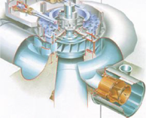
Figure 1, An Image of a Francis Turbine.
Water enters the scroll-cage from the left and goes around the runner, guided into the runner by guide vanes, also called wicket gates, which can be adjusted, and exiting down the draft tube into the tail race and into the Youghiogheny river. The wicket gates can control the flow, and hence the amount of power produced, but I don’t believe they do that at Deep Creek.
The big pipe on the lower right is a duct that contains the pressure relief valve. The exit of the duct is presumably connected to a tube that exits into the tail race.
So one can see clearly two opportunities for leakage: 1) water leaking though the wicket gates when the wicket gates are supposed to be closed, and 2) water leaking through a bad pressure relief valve. The image below shows the location of the wicket gates and how worn wicket gates could leak water through the turbine via the draft tube into the tail race, Figure 2.
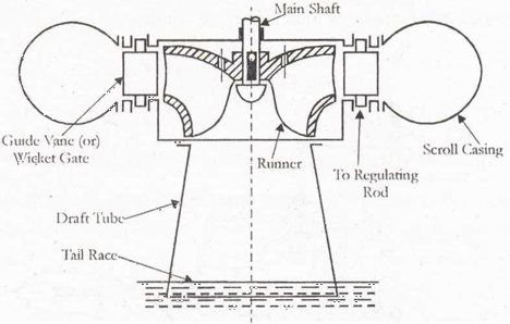
Figure 2 - Draft Tube.
The other leakage that Brookfield mentions is via drain valves in the scroll-cage. I don’t know how big they are and how many there are and where the leakage flows to. From the diagram above the leakage may wind up directly into the tailrace. Is this a difficult measurement to make? I don’t think so.
The letter to John Grace from Brookfield, dated April27, 2012, mentioned a problem with the turbine inlet valve (TIV). The image below shows where the TIV might be installed (image from the web, not necessarily the Deep Creek facility). It’s the valve on the left hand side of the image. This is most likely the main control valve to start and shut down the generator. This is certainly a critical item in the facility. As a side note, the middle controller shown in the image operates the wicket gates or guide vanes.
To repair all turbine related issues would require a reliable TIV. (Again, I don’t know much about how operations are conducted.) There should be a large pressure on the valve when it is in closed position.
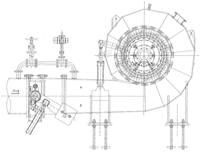
Figure 3 - Control Valves
It’s pretty simple to measure the total leakage from the system: measure the flow in the tailrace when the generator system is supposed to be completely shut down. Is that the total number they state in the letter? Is the different between the Unit 1 and 2 measurements and the total, the amount going through the pressure relief valve and scroll-cage drains? I don’t know how they do the individual measurements. I don’t know what kind of sensors are installed.