Piet's Notes on Deep Creek Lake Science
Sensible Technologies - The Science of Deep Creek Lake
Deep Creek Lake is the base of the Deep Creek Hydro Project. You’ve probably heard that it uses “Francis” turbines. In a Francis turbine the water passes through a snail-shaped scroll case, through wicket gates, that control the amount of water, and into the submerged runner. The curved blades of the runner change the momentum of the water, which produces a net force or reaction in the turbine. This reaction has a tangential component that turns the wheel, and the wheel is attached to an “Exiter” that generates electricity.
The Francis turbine was developed by James B. Francis in Lowell, Massachusetts. It is an inward-flow reaction turbine that combines radial and axial flow concepts.
Figure 1 is taken from Ref.2 and shows a schematic of the turbine.
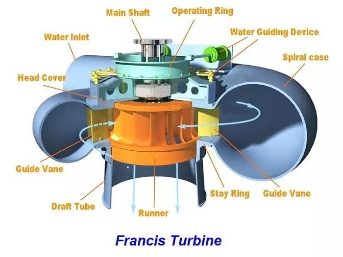
Figure 1 - Schematic of a Francis Turbine
There are other types of turbines, but I won’t go into how they operate and what their potential issues are. Information about others can be found in References [3] and [4].
The Francis turbines are suitable for a pressure drop from heights of 20 to 900 m with variable flow rates from 1 to 20 m³/s, or in English units, from 33 ft to 330 ft and 35 cfs to 710 cfs, give or take.
The Deep Creek Hydro project has the following atributes:
The Supply of Water:
| Feature | Elevation, ft MSL |
|---|---|
| Dam Crest | 2475.0 |
| PMF Level | 2472.8 |
| Top of the Core Wall | 2466.5 |
| Spillway Crest | 2462.0 |
| Normal Max. Pool | 2462.0 |
| Intake Tunnel | 2415.0 (center line) |
| Generator Floor | 2046.5 |
| Turbine Distributor | 2034.0 (center line) |
| Normal Tailwater | 2024.0 |
Note: PMF stands for Maximum Probable Flood.
The Characteristics of the Turbines:
| Characteristic | Value |
|---|---|
| Year Installed | 1925 |
| Rated Output | 12,000 hp |
| Rated Net Head | 400 ft. |
| Discharge | 320 cfs |
| Speed | 514 rpm |
| Number of Generators | 2 |
| Rated Output | 12,000 kVA |
| Rated Output | 9,600 kW at 0.9 PF |
| Controls | Hydraulic |
| Valves | 2 Johnson Needle Valves |
| Valve Size | 6 ft. 3 in. |
NOTE, Page 2-10 of Ref. 5 lists the Power Factor, PF to be 0.8 while the table above shows 0.9
The Characteristics of the Lake
| Characteristic | Value |
|---|---|
| Max Surface Area | 3,900 acres |
| Max Area at | 2462 ft |
| Usable Storage | Above 2,425 ft |
| Usable Storage Volume | 93,000 acre-feet |
| DCL Drainage Area | 64.6 sq. miles |
A concrete intake structure is located upstream of the spillway on the north-western shore of the lake to direct water from the lake into the power tunnel. The intake structure is equipped with trash racks, trash rake, control gates and gate hoists.
The power tunnel is 9 ft. in diameter, horse-shoe shaped and is concrete lined throughout its 6,652 ft length from the intake to the surge chamber. The tunnel has a gradient of 0.8 percent in this section. Forty six feet downstream from the surge chamber, the tunnel is lined with steel for approximately 393 ft where it then bifurcates over a transition length of 57 feet into two 700 foot-long steel penstocks. The diameter of the penstocks varies from 6 ft. 3 in. to 6 ft. 0 in. The penstocks feed the two turbines in the powerhouse, which in turn, discharge into the Youghiogheny River through a 435 foot-long excavated tailrace.
The surge chamber is of concrete and steel construction. It is 30 ft. in diameter and 145 ft. high and extends approximately 52 ft. above ground level.
To quote from Ref. 1: “The available head in a power plant is given by the difference of the high water level and the tail race water level and can be expressed as:
$$ P = \rho g H Q $$
Losses in the process must be taken into account. The hydraulic efficiency of the turbine is defined as the ratio between the utilized head and the available head. By definition the available head is established by subtracting the total head at the outlet of the draft tube, from the total head at the inlet of the runner. By this definition, losses in the conduit system, head- and tail race tunnels are not included in the turbine efficiency.
The hydraulic efficiency of the turbine can then be expressed as:
$$\eta_h = \frac{H_n}{H}$$
Where
\(H_n\)
is the net head, accounted for losses developed in the turbine and draft tube.
At the inlet of the spiral casing, the energy is mainly pressure energy. The flow is evenly distributed around the circumference of the casing and passes the stay vanes and guide vanes before it enters the runner. Through the stay- and guide vanes the flow is accelerated, converting pressure energy to velocity energy. At the inlet of the runner the energy is typically 50% velocity energy and 50% pressure energy, depending on the reaction ratio of the turbine. The reaction ratio is defined as the pressure drop through the runner divided on the net head.
In other words, the reaction ratio is the pressure part of the total energy converted into mechanical energy the runner, and for middle and high head Francis turbines the value is typically 0.48-0.50, dependent on the blade design, while for a Pelton turbine, another kind of water turbine, it is always zero since the pressure is the same before and after the runner.
The vertical Francis type turbines each rated at 12,000 horsepower at 400 ft. head (see the table above). It’s not stated, but presumable “net” head is after all frictional losses have been accounted for.
“The two Francis turbines in the powerhouse have a total hydraulic capacity of around 640 cfs. Based on index testing of the units in 1992, Penelec normally operates the turbines for maximum efficiency. At maximum efficiency, flow through the turbines is about 560 cfs."[p.2-18 of Ref.5]
“The annual plant factor is approximately 18 percent, based upon the summer net capacity rating of 18 MW."[p.2-14 of Ref.5]
“The average energy production of the plant over the 65-year operating period is 28,300,000 kWh per year."[p.2-14 of Ref.5]
When one uses $0.12/kWhr, the gross income from electricity production only would be about $3.4M
Normal tailwater level when both units are operating is at or near an elevation of 2,024 ft. The variation of tailwater level from elevation 2,024 feet is less than 1/2 percent of the total head on the plant.[p.2-18 of Ref.5]
“During two-turbine operation, flows in the river increase by between 500 and 640 cfs. During one-turbine operation, river flows increase by between 250 and 320 cfs.” [p.3-7 of Ref.5]
The gross capacity of a hydropower plant in a river can be calculated as mentioned in the above equation,
$$P = \rho g H Q$$
Plugging in numbers for the variables: Density of water: 1,000 kg/m^3 Gravitational Aceleration: 9.8 m/sec^2 Head: 122 m (400 ft) This should be “net” head after all friction lossess have been accounted for Discharge: 9 m^3 /s (320 cfs)
Gives P = 10,760,000 Watt or 10.8 MW
To this one must apply the turbine ’efficiency’, which may be 0.8 or 0.9.
Not far from the stated 9 MW per turbine.
Note the following from the 1993 report (Ref.5): “The two Francis turbines in the powerhouse have a total hydraulic capacity of around 640 cfs. Based on index testing of the units in 1992, Penelec normally operates the turbines for maximum efficiency. At maximum efficiency, flow through the turbines is about 560 cfs. [p.2-18 of Ref.5]”
So using 560 (or 280 per turbine) rather than 320 gives P = 9.4 MW.
Then there is also the ‘power factor’ which has been stated as 0.8 [p.2-8 of Ref.5] In AC circuits, the power factor is the ratio of the real power that is used to do work and the apparent power that is supplied to the circuit.
“A weir is located just downstream from the dam (see Figure 3-15 of Ref.5) on Deep Creek. During normal operations, discharge over this weir is usually less than 1 cfs. This water originates from either groundwater or from seepage through or under the dam."[p.3-14 of Ref.5]
“Indeed, the location of the upper limit of the buffer strip at elevation 2,466 ft. (plus 25 horizontal ft.) was at least partly based on consideration of an adequate margin for maximum credible flood (MCF) heights."[p.3-20 of Ref.5]
“The reach of the Youghiogheny River examined in this report is part of a larger reach that was designated in 1971 as a state wild river. Over 95 percent of the land in the wild river corridor was privately owned in the mid-1970s (U.S. Congress 1979). Exceptions at that time included several segments of Garrett state Forest located within a mile of the river and the river itself. The state of Maryland owns river beds, but recognizes landowners who hold title to riparian land from patents issued prior to March 3, 1862 as also having an ownership interest in the river bed. The public retains the rights to fish and navigate rivers in Maryland (U.S. Congress 1979). The State of Maryland has been acquiring lands from willing sellers within the designated river corridor and now owns about half the corridor acreage (Maryland Department of Natural Resources, 1991)."[p.3-24 of Ref. 5]